Goal:
The goal of this PCB was to create a compact electronic board that could control all the components and logic of a thrust vector control rocket. This was part of a larger project to build a model rocket that could land itself. The PCB needed to control the servos for all the components in the rocket, make decisions based on altitude and angle, log data to a micro SD card, and ignite motors. Furthermore, it had to be battery-powered and capable of withstanding the forces generated by the rocket motor during flight.
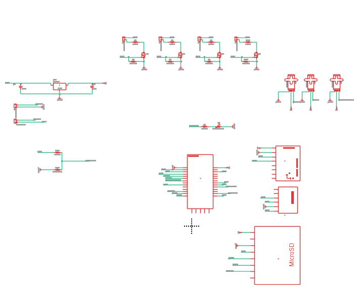
Schematic Design:
I designed the PCB in Fusion 360, using BPS Space’s PCB as a rough reference. I started by selecting the Teensy 4.0 due to its compact size and availability of prebuilt libraries for the sensors I planned to use. Next, I added sensors to the design: the MPU6050, which includes both an accelerometer and gyroscope for accurate flight angle tracking, and the BMP280, a common sensor for measuring altitude in these applications. To enable flight data logging for testing and future improvements, I incorporated a microSD breakout board. I chose to use only through-hole components since I don’t have the equipment to solder surface-mount parts, and breakout boards are much easier to work with. Additionally, I included terminal blocks connected to MOSFETs to handle 12V outputs for igniting motors or powering other high-demand components. Throughout the process, I maintained a spreadsheet detailing all parts, their costs, and purchase links.
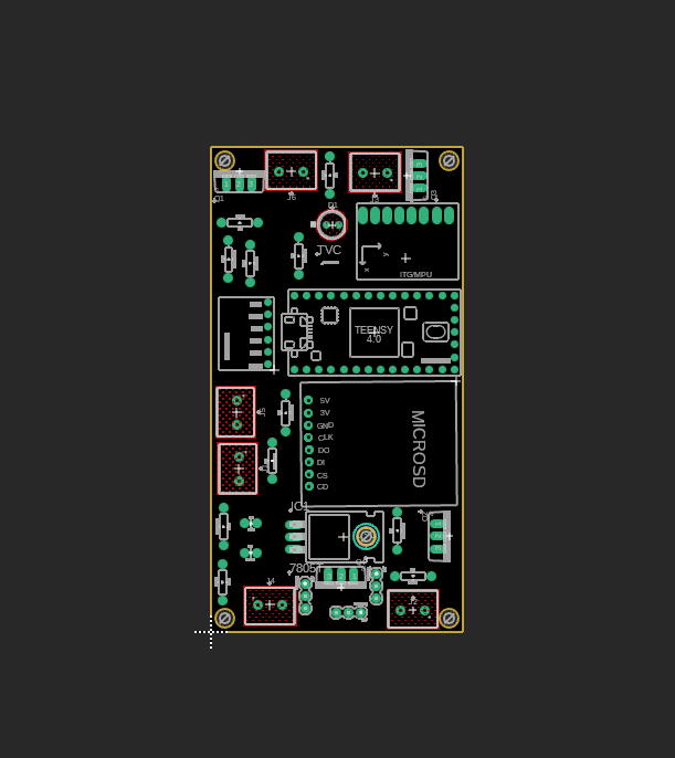
PCB Layout:
For the PCB layout, I chose a 4-layer board to dedicate separate planes for GND, 5V, 12V, and 3.3V power rails, as I prefer to avoid routing power traces manually. I began by designing a board small enough to fit inside the rocket without taking up excessive space. Then, I placed the largest components first, gradually positioning the smaller ones around them. Finally, I manually routed all the traces to complete the connections across the entire board.
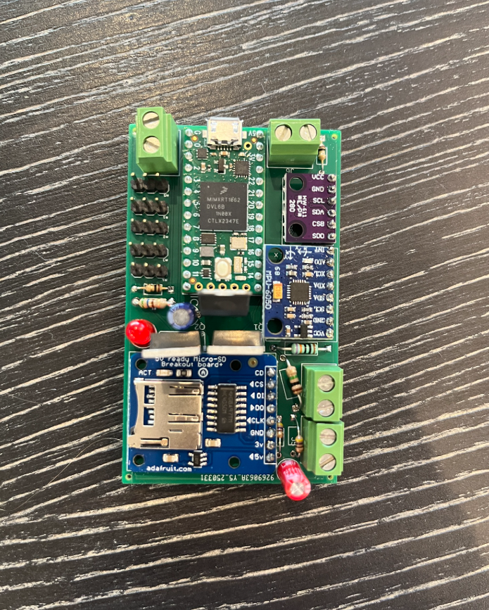
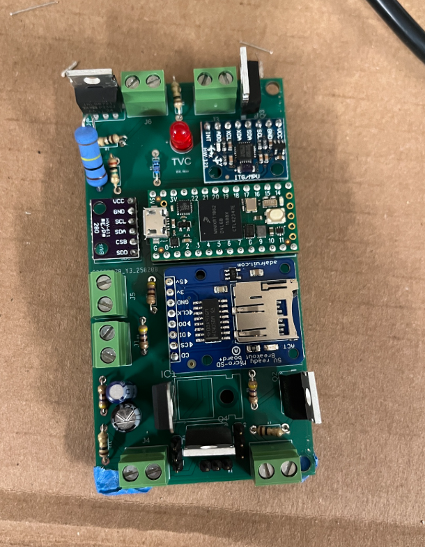
Fabrication & Assembly:
The board was manufactured by JLCPCB. After receiving the PCB along with parts from Digi-Key and Adafruit, I soldered all the components onto the board by hand. I didn’t have flux in my solder at the time, which made the soldering process significantly more difficult.
Firmware:
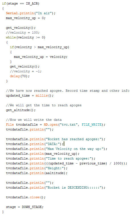
I used the Teensyduino add-on for the Arduino IDE to program the PCB. I began by initializing all the sensors using pre-installed libraries available in the Arduino environment. To keep the code organized, I implemented a simple state machine. I wrote functions to calculate velocity and used a Kalman filter to combine data from the accelerometer and gyroscope for accurate angle estimation. Additionally, I implemented basic SD card logging to record flight data for post-flight analysis.
Challenges:
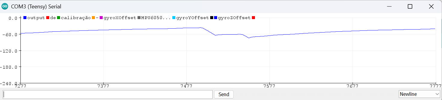
The main challenge I faced was calculating the angle from the MPU6050. At first, I tried calculating the angle manually using only the accelerometer. However, whenever the PCB was moved or subjected to g-forces, the angles would spike dramatically, sometimes jumping to over 2000 degrees. This was a problem, since the rocket would be experiencing g-forces during flight. I then switched to using just the gyroscope, but over time the angles drifted significantly, making them unreliable. Finally, I implemented a Kalman filter, which combines data from both the accelerometer and gyroscope to produce a more stable angle. This solved both problems as it removed gyroscope drift and improving accuracy under g-forces. The angle still spikes briefly during the transition into g-forces, but once stabilized, it remains accurate. This is because the accelerometer computes angles based on acceleration vectors, and under sustained g’s, these vectors form a triangle similar to the one formed at rest. So, after the initial spike, the angle returns to a correct value even while under acceleration.
Tools & Technologies:
Fusion 360, Sensor fusion, Teensy 4.0, I2C protocol, PCB creation, state machines, soldering, Arduino IDE
Outcome:
While the PCB has not yet been tested in a launched rocket, I have conducted numerous bench tests and confirmed its functionality across all systems. Based on these results, I am confident that it will perform as expected when integrated into our larger rocket project and contribute to a successful flight.
Reflection:
This project has been the most valuable and educational one I have worked on so far. It has given me a solid understanding of designing custom electronics tailored to specific purposes, and strengthened my skills in both hardware and software development.