Design:
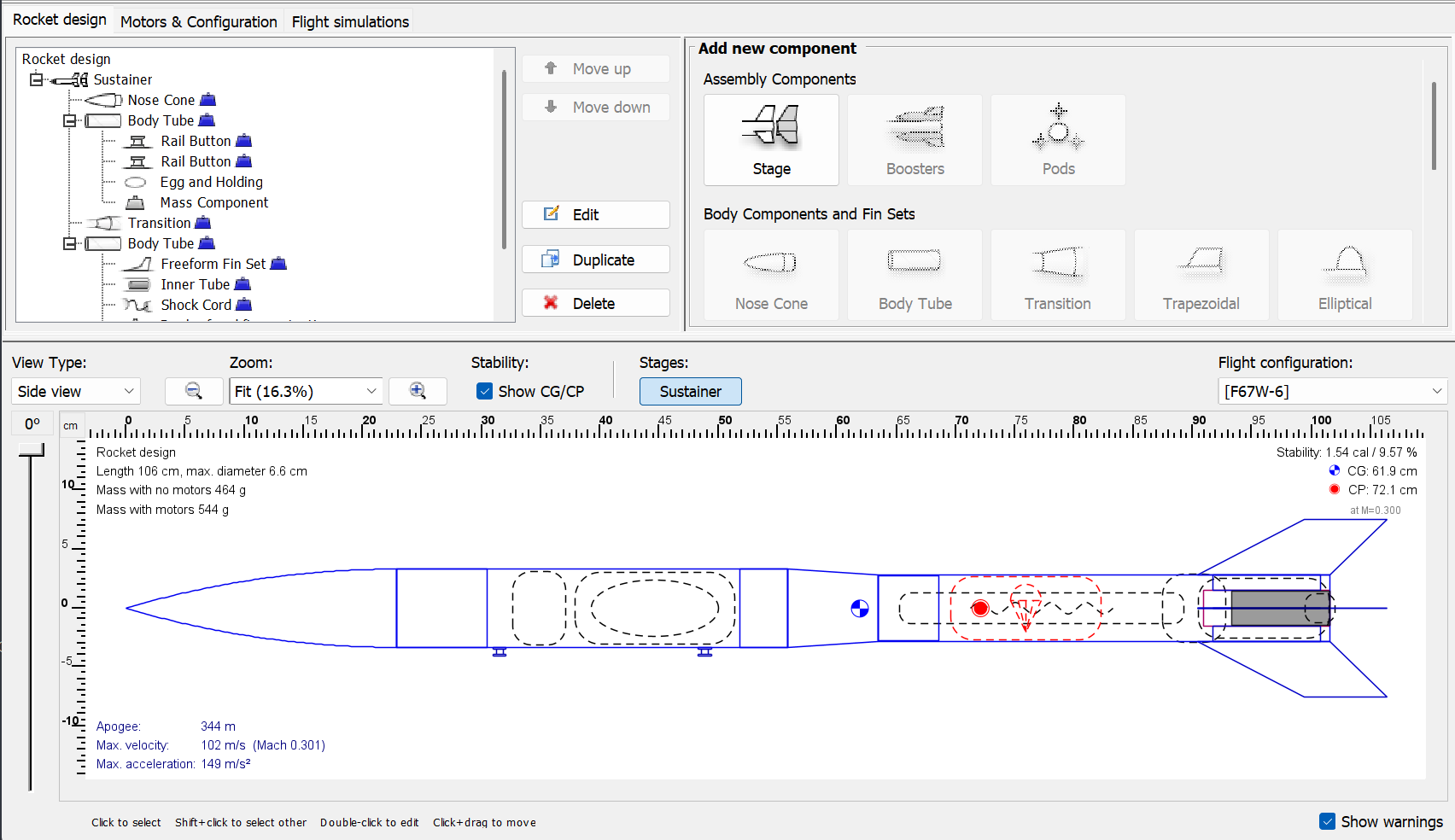
The first step in building a rocket is defining its specifications and goals. For me, this typically involves designing rockets for competitions like the American Rocketry Challenge(ARC), which requires adhering to rules for part sizes, dimensions, and weights. I begin by creating a basic outline in OpenRocket, a usefull tool for planning aspects such as motor selection, dimensions, and flight characteristics. However, I don’t rely on OpenRocket’s built-in parts library, as it often contains incorrect data for weight, length, or diameter. Instead, I look at Apogee Rocket for parts and manually create custom components in OpenRocket that match Apogee’s specifications. This approach gives me much more realistic and reliable simulations, as the parts I order will match the simulation with certainty.
Construction:
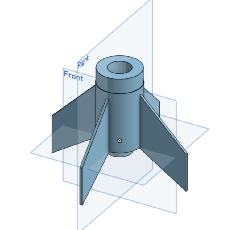
While designing the rocket in OpenRocket, I generate a bill of materials to easily order all the necessary parts once the design is complete. Recently, I’ve started 3D printing(with abs) nearly half of the rocket to reduce costs and improve durability, since plastic tends to be stronger and more consistent than cardboard. The components I typically print include the nose cone, transition, and a combined motor mount and fin unit. After gathering all the parts, I assemble the rocket using super glue, and I create snug fits between removable parts using tape.
Testing:
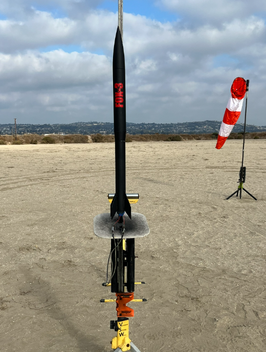
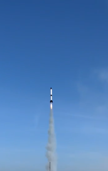
After the rocket is fully assembled, I bring it to a local rocketry event for launch testing. At the site, I prepare the rocket by setting the altimeter, packing the parachute, and preparing the motor. I also create a data sheet to record important information such as total weight, payload, and type of motor. When ready, I mount the rocket on the launch rail, insert the ignitor, make sure the rocket is ready to launch, and start recording. After launch, I recover the rocket and collect all flight data from the altimeter. I then log the results such as apogee, velocity, and other notable events into my flight log for analysis and design improvements.
Analysis & Correction:
After each launch, I evaluate the flight data and use it to refine my simulations. I adjust parameters, such as the drag coefficient in my Simulink model to better match the rocket’s real-world performance. For example, if my rocket reached 830 feet on a test flight but the target altitude is 790 feet, I modify the simulation to determine how much additional mass would be needed to reach the desired altitude. I then apply that same mass adjustment to the physical rocket for the next test. This iterative process helps me fine tune performance while reducing the number of tests and overall cost. Once the rocket consistently meets expectations and proves reliable, I usually build one or two identical replicas. This ensures that I can continue testing and launching without delays, even if one rocket experiences damage or failure.
Challenges for ARC(2025):
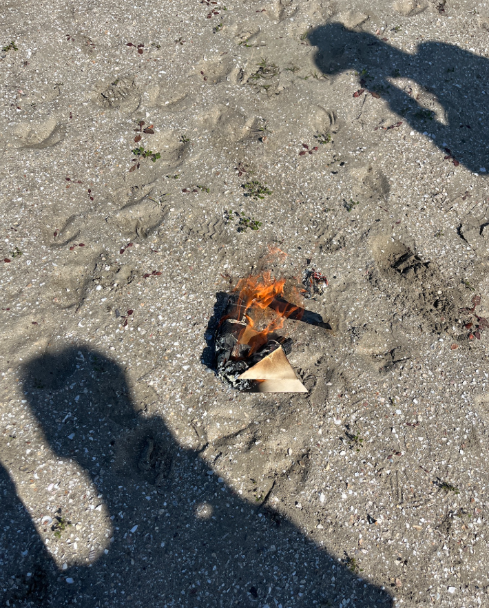
The two main challenges we faced were motor consistency and launch stability. For ARC, we use single-use motors like the F20W with a 7-second delay. The problem was that the motors weren’t consistent—rockets with nearly identical setups and flight paths could vary by over 100 feet in altitude. Even worse, in two launches, the motor was faulty and lit both the main and ejection charges at ignition, which caused the rocket to catch on fire and separate immediately. To fix this next year, we’re planning on using reloadable motors, which are supposed to be more consistent and cost-effective. Not many teams use these because they’re harder to deal with as you have to assemble them before every launch, but we think it’s worth it. The second challenge was launch stability. A lot of our rockets came off the rail at about a 30-degree angle before correcting. This was most likely because our rail buttons were too close, so the rocket didn’t get enough initial guidance to stay vertical. We’re planning to make our rail buttons farther apart next season.
Tools & Technologies:
Open Rocket, Iterative Design, Simulink, 3d printing, Excel, Hands on Construction.
Outcome:
I successfully (and sometimes unsuccessfully) designed, built, and tested several rockets that met their specified goals. It’s been a very educational experience not just learning about rockets, but doing it all in a hands-on way. The best part has been understanding why things happen, not just knowing that they do.