Goal:
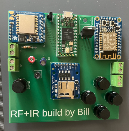
To create an electromagnetic multitool from a PCB that can understand, write, and receive a variety of signals like WiFi, IR, and RF. Furthermore, it needs to have onboard control and a UI.
Process:
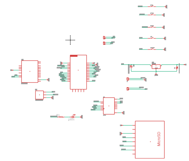
I began by compiling a bill of materials, sourcing components from Digikey and Adafruit to ensure each part had a compatible digital footprint. Once finalized, I designed the circuit using Fusion 360’s PCB tool (formerly Eagle), carefully routing connections and planning for efficient layout. Like with my custom rocket PCB, I used a Teensy 4.0 as the onboard control unit. For signal capabilities, I included a 433MHz LoRa module for RF communication, an IR receiver/transmitter pair, and an ESP8266 for Wi-Fi functionality. After finalizing the design, I sent the board to JLCPCB for manufacturing. Once the PCB arrived, I soldered the components and began developing the firmware. I wrote functions for each component and integrated them into a simple user interface controlled by onboard buttons and a small display.
Challenges:
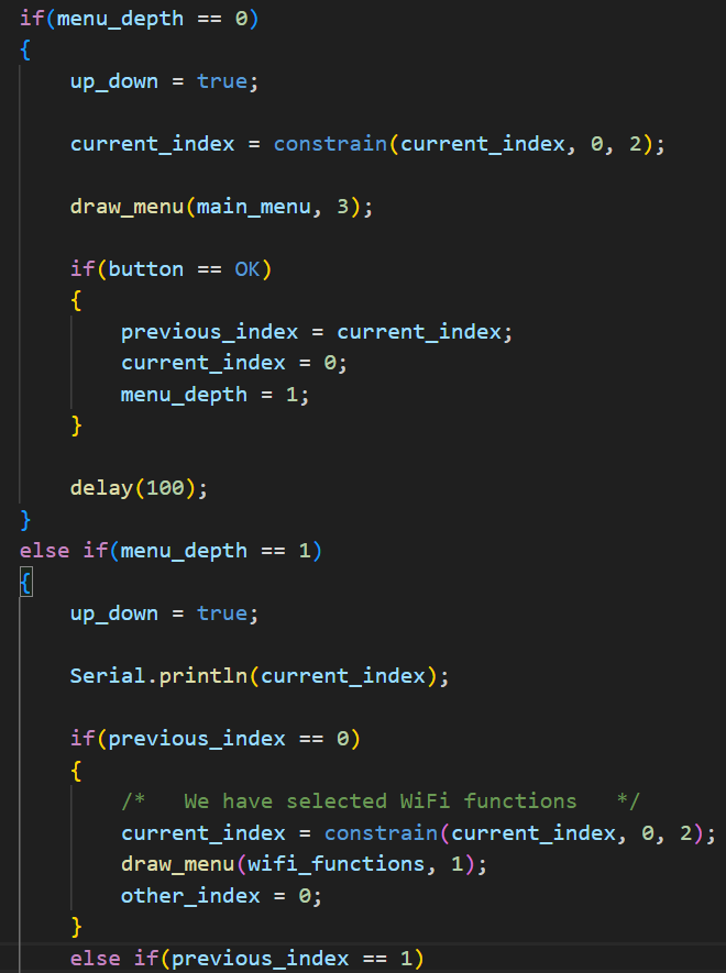
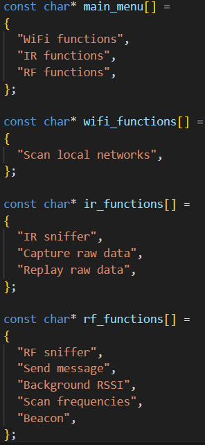
The most challenging part of this project was designing a working UI that could smoothly navigate between modes and functions. My interface had three layers: home, component, and function, which required tracking multiple indices and button inputs. This complexity led to numerous bugs, making UI development one of the most time-consuming aspects of the project.
Tools & Technologies:
LoRa modules, IR functions, WiFi, C++, Basic UI system, PCB design, UART.
Outcome:
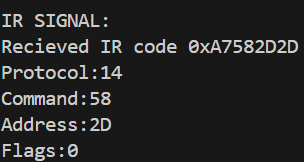
This custom PCB successfully manages both receiving and transmitting multiple signal types. It can read and send IR codes to control devices like TVs, generate an RF beacon for signal testing, and perform a range of other wireless functions.
Reflection:
This project was incredibly valuable, teaching me how to control and integrate various communication technologies. The skills and insights I gained will be essential for my future projects.